During the summer of 2021 I built a garden workshop. This was a joint endeavour with my partner, who designed and specified the form and finish (credit for the CAD drawings goes to her). The basic construction follows the methodology of Oakwood Garden Rooms who’s YouTube channel proved invaluable guidance through the process. I also bought from them parts for the rod system for the footings, and a ‘build pack’ that crucially provided a preliminary materials list. This note documents the process of the design and build, but making sure not to reveal any of the details supplied in the Oakwood Garden Rooms build pack.


Groundworks
After clearing and levelling the workshop site, holes were dug for each of the steel rod footings. The setting out of these was carefully determined with string lines since the base timbers slot directly onto the rods with a relatively small amount of tolerance, and determining the overall size and shape of the base.


Base
The base is constructed with a frame bolted down onto the 24 mm threaded rod piles and joists supported with hangars bridge between the frame timbers. 100 mm insulation is cut and inserted between the joists, and supported below from falling by treated batten fastened to the joists. All gaps were filled with expanding foam. A layer of breathable roofing sheet is laid over the base before the 22 mm chipboard floor sheets are glued and fastened down.


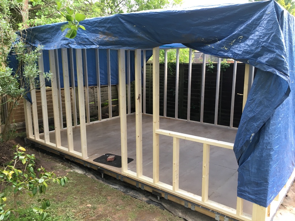
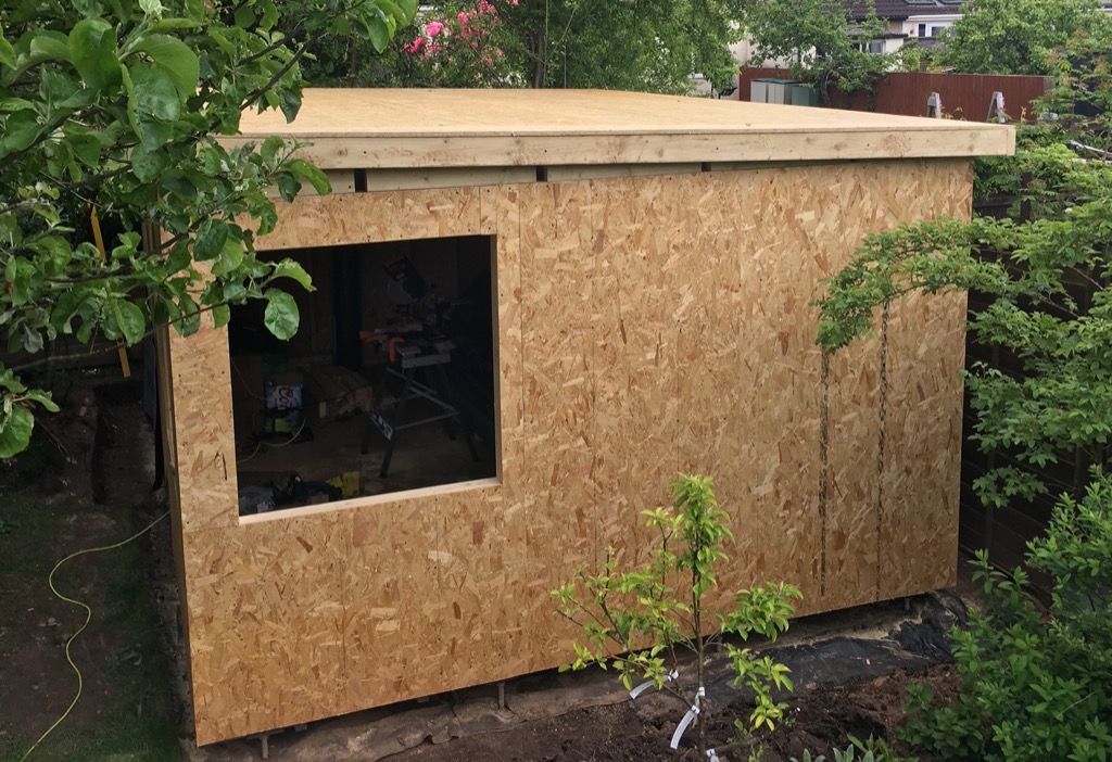
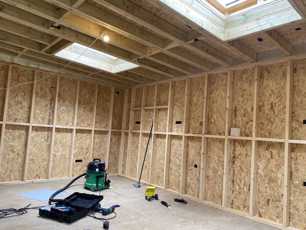
Structure
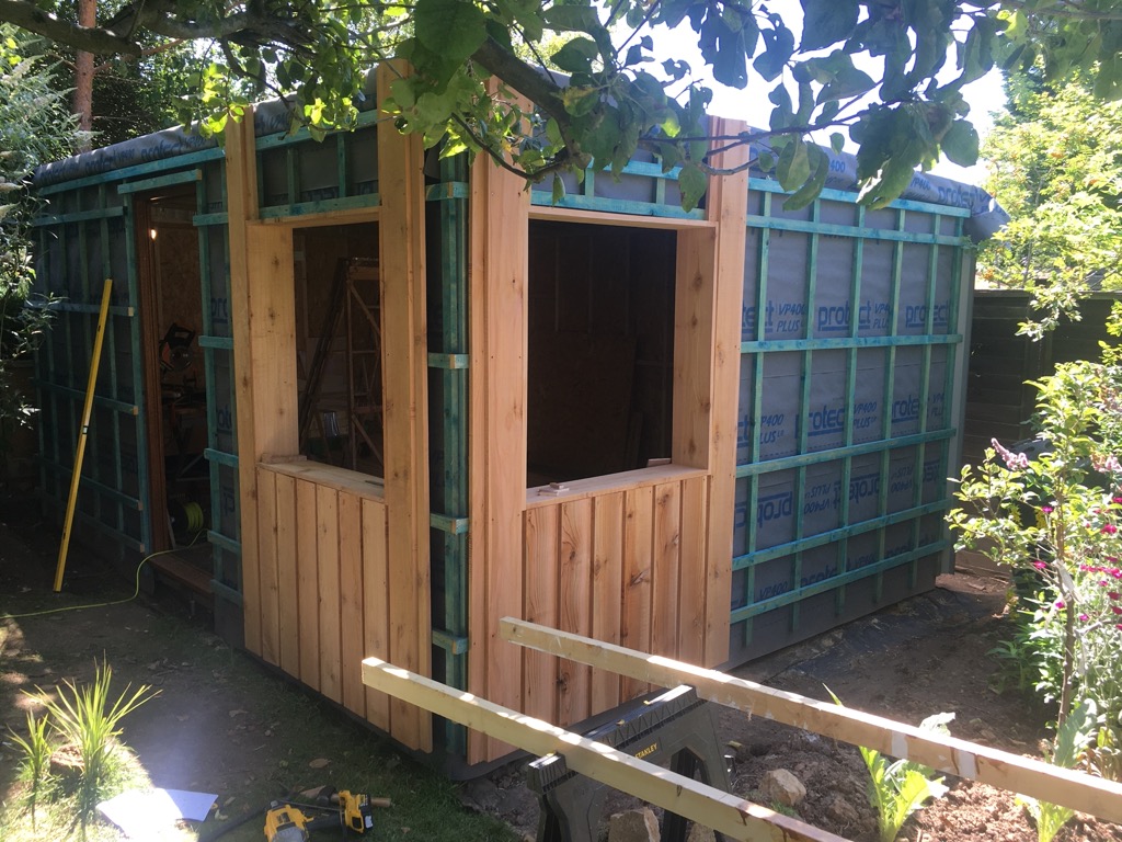
The walls are constructed using 50 x 100 mm studwork timbers and covered with 12 mm OSB sheet. The roof is constructed with 47 x 125 mm timbers, doubled up to span the wall-to-wall gap, and covered in 18 mm OSB tongue-and-groove roofing sheets.


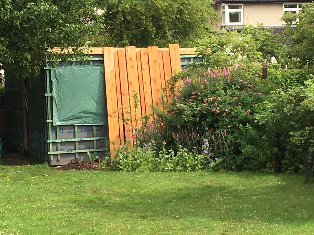
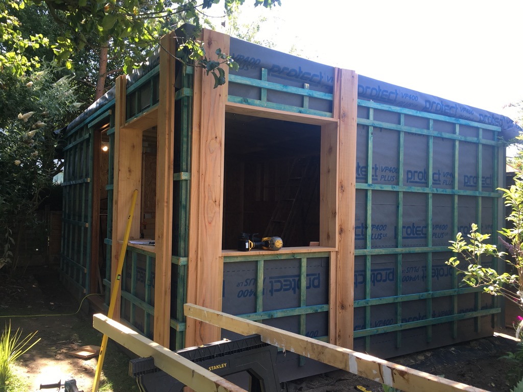
Waterproof wrap and batons
The walls are covered in a breathable waterproof membrane (standard roofing sheet) and two perpendicular layers of roofing batten to support the vertical cladding.


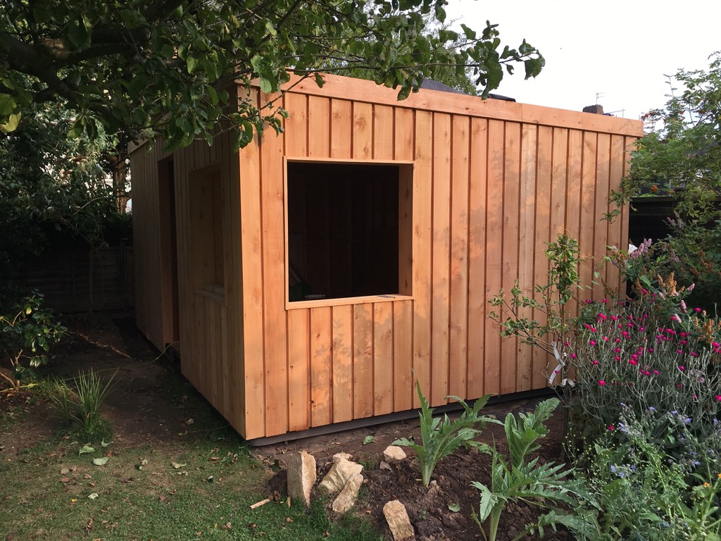
Cladding
The cladding is made from rough-sawn cedar, sourced from Gladstone Sawmills in South Wales. The vertical pattern is 150 mm widths separated by a 25 mm gap, fastened to 75 mm widths sitting behind.


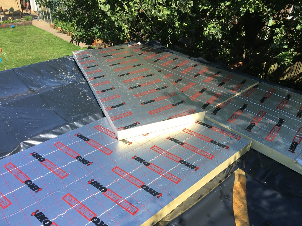
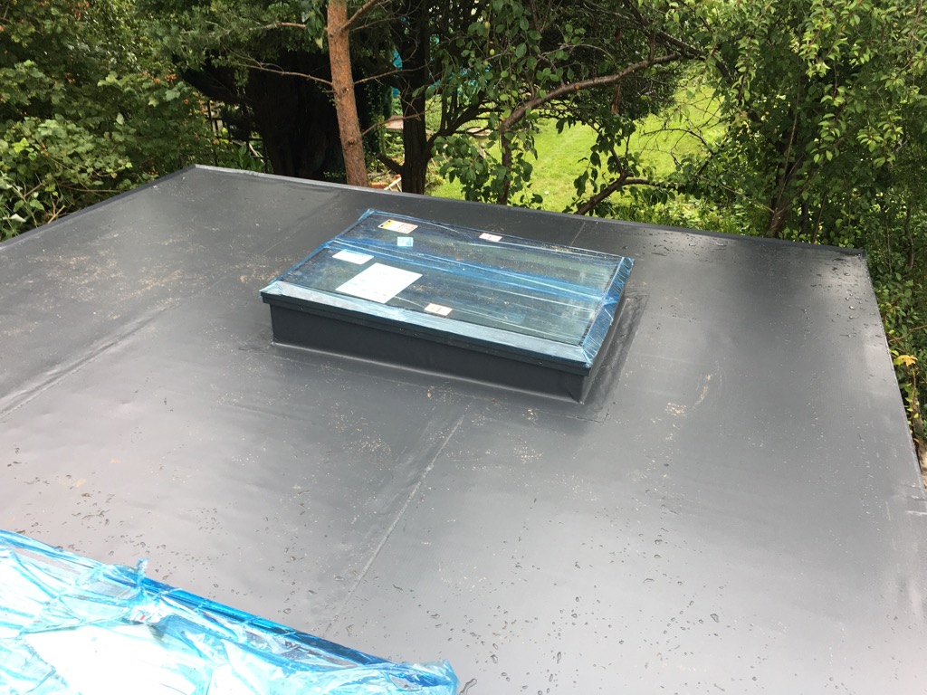
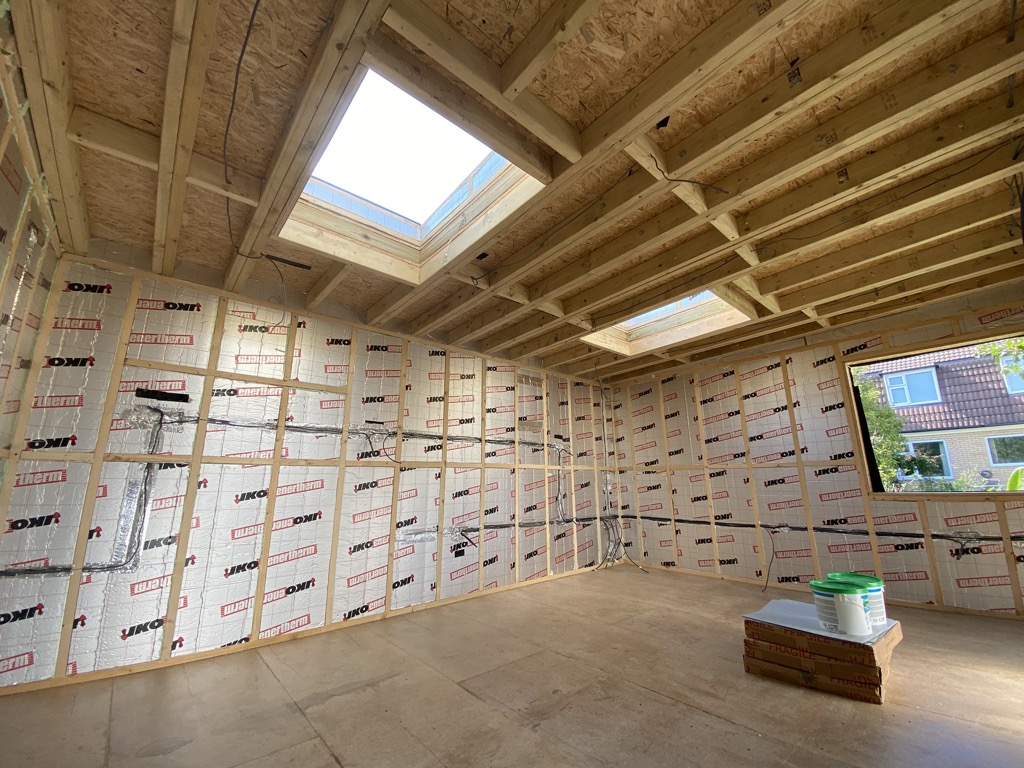
Warm roof and rooflights
The roof is built up following a warm roof construction. On the bottom deck of 18 mm OSB, a 100 mm perimeter is built around the edge and roof light openings. A damp-proof membrane is laid in the resulting area, and 100 mm insulation boards laid on top and packed tightly. The roof is covered with a Bauder single-ply roofing system, installed by County Flat Roofing. The roof lights measure 1,200 x 900 mm external dimensions.


Buildups
The following two images show the buildups of the roof and wall. The roof buildup consists of (starting inside) 125 mm structural timber, 18 mm OSB bottom deck, 100 mm insulation perimeter, 18 mm OSB top deck, roofing felt, Bauder membrane, roof light upstand and rooflight. The wall buildup consists of (starting inside) 100 mm studwork, 12 mm OSB, waterproof membrane, two layers of 25 mm roofing batten, two layers of 20 mm Cedar board. Both buildups do not show the 15 mm internal plywood panelling that was installed later.


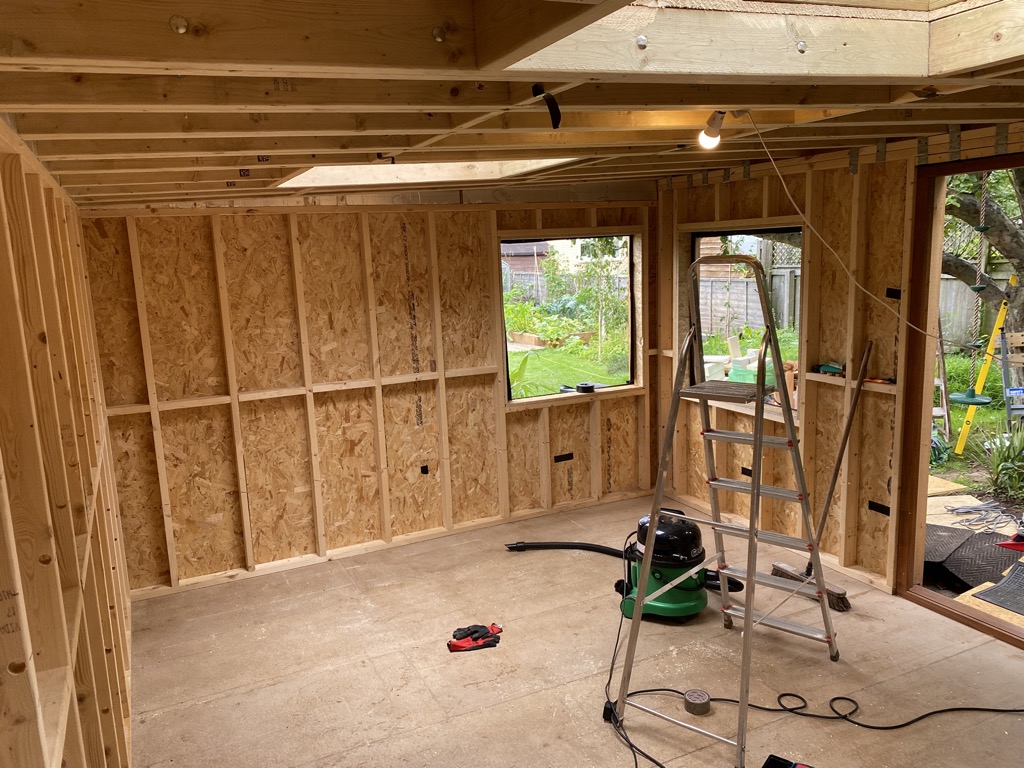
Windows
The two windows are 1,040 x 1,040 mm double-glazed aluminium casement, supplied by Panoramic Windows.

Internal fit out
Socket and switch positions
Positions of sockets, lights and wiring was marked out using tape.
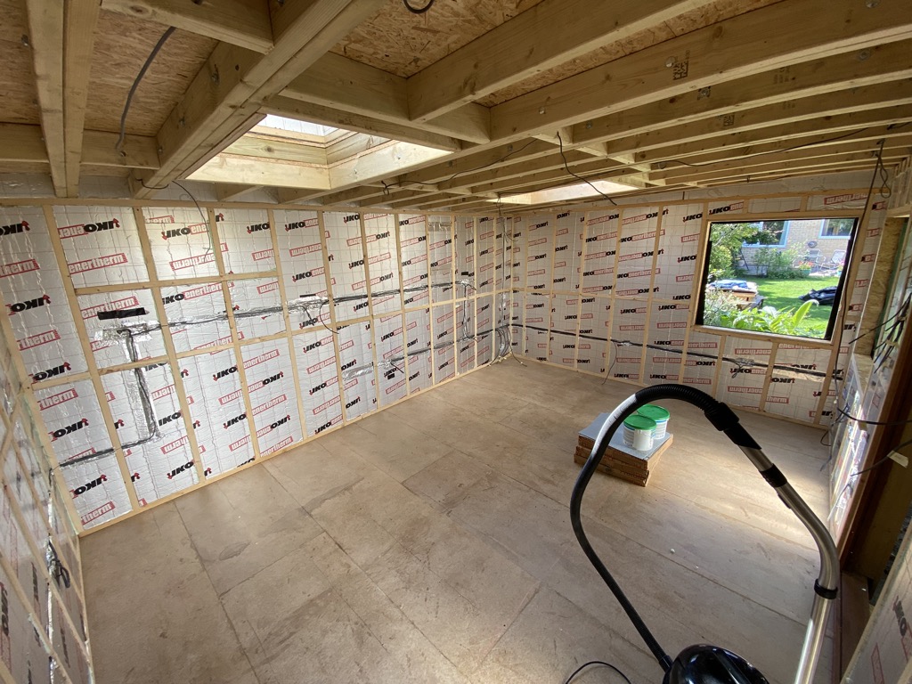
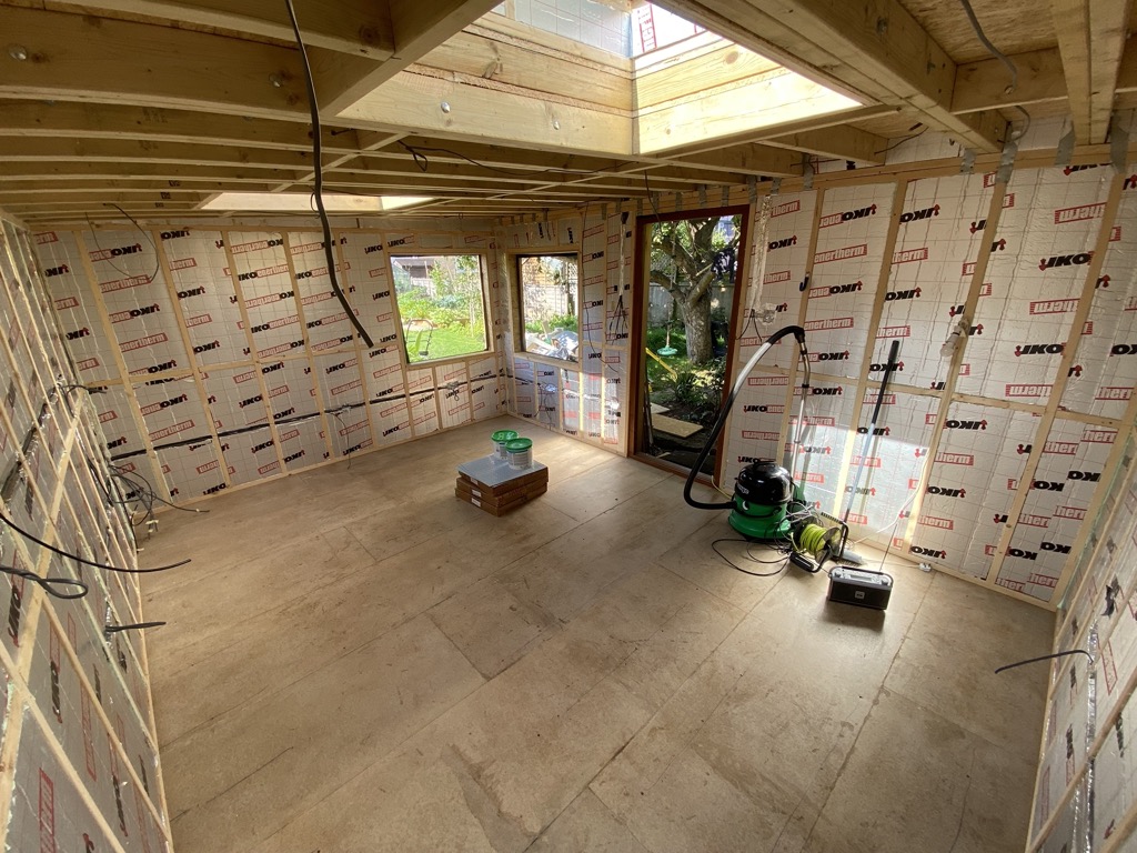
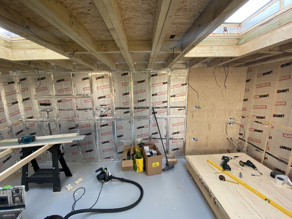
Wall insulation
The wall carcassing was filled with 80 mm sheet insulation, into which channels were created for the wiring. In order to create a moisture barrier, all sheets were taped together with aluminium foil to create a single air-tight surface. Special attention was paid to the interaction between the roof and walls, where otherwise it would have been easy to have areas of missing or shallow insulation.


Wiring and first-fix electrics
Wiring for electrical and data sockets and all the lighting was pulled though holes in the carcassing. We created two separate socket circuits (right and left), and a circuit for wall-mounted heaters. The lighting is divided into three ceiling circuits branched off the switches, plus an outdoor light.

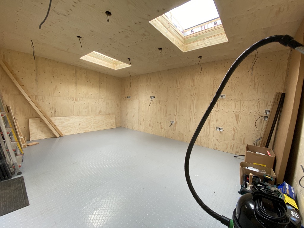
Boarding
The internal finish is done with 15 mm WISA-Spruce Special boards fixed to the walls and ceiling.


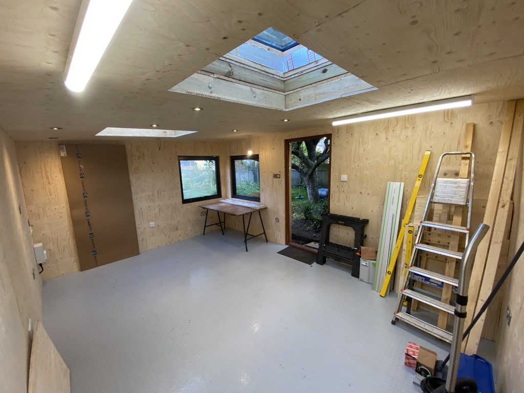
Second-fix electrics
With the second-fix electrics completed, the workshop was operational.
More details of the final details to be added as they are completed…
Drawings
The following drawings are taken from the Revit model of the workshop.


