I recently moved into a Cornish Unit Type 1 house, and with my involvement with The CHEESE Project I was keen to perform a thermal-imaging survey to better understand how well the building performs thermally. Also, with the first few months in the house being in winter and it feeling very cold in places, I had extra motivation to find out where heat was being lost, and to try and resolve some faults. I have written this note to record what I found as a case study that others may find useful, from the point of view of understanding the benefits of using thermal imaging to assess building performance, and to see the kinds of thermal faults that are standard among domestic buildings. Included also are some simple remedial measures that I took to address thermal faults. The emphasis of these were low cost and low effort to improve the house in the short term, and particularly during the winter. With plans to renovate and extend in the next couple of years, the survey would also provide guidance on where more significant interventions could be targeted.
I followed the methodology of The CHEESE Project to perform the survey (more details about home surveys and the process). To summarise: the best thermal imaging results are obtained when there is a good temperature differential (at least 10 degrees) between inside the building and outside. For this reason, winter is the best period, with the building heated for 24 hours to warm up the fabric rather than just the air inside it. A blower door fitted to an external door is used to reduce the internal air pressure and accentuate any draughts. Once the heating is switched off, the house will start to cool down by thermal conduction through materials and ingress of cold air through draughts. While this is happening the thermal camera is used to capture the effects of any areas of rapid cooling, ie ‘thermal faults.
External
I did the survey in December, and the external temperature was close to 0 degrees. The images below show the back of the house in infra red (thermal) and visible light. There is little to learn from the thermal picture, and note that the windows will be reflecting some of the cool night sky.
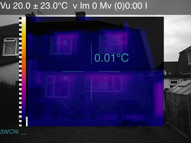

There are a few things to remember when inspecting the thermal images. The thermal image is overlaid on the larger visible-light image, the temperature value is the measurement taken at the cross hairs, and often each image is taken with a particular temperature range to give the best contrast to the subject of the image. The temperature range is given in the top left-hand corner, and the black and white squares show the degree increments along the colour scale. In the thermal image above left, the range is centred on 20 degrees plus and minus 23 degrees. All the thermal images in this note use a colour palette called ‘ironbow’, which I find most intuitive, there are however other choices such as rainbow and greyscale.
Front door
The area by the front door was noticeably cold when walking past it. The thermal images reveal cold single glazed glass sections (at ~15 degrees compared with ~22 degrees ambient temperature of the hallway), and draughts, particularly at the bottom where the temperature drops to 10 degrees.


To tackle the leakiness of the front door, I added some acrylic secondary glazing to the glass sections and blocked up the letter box with glass fibre insulation and a wooden plug (there is another letter box in the porch). I admit this was not an elegant solution, but it was quick and cheap. The look of acrylic could have been improved by using magnetic strip for attaching it, also allowing for it to be removed. But since the door will be replaced in the next 18 months, I was not too worried.


Windows
The house has uPVC double glazing throughout (installed within the last 10 years), but a main finding of the survey was the windows had some significant thermal faults.
Leaking trim
The most obvious fault was draughts around the edges of the frames, from behind a plastic trim. In the left-hand images, the cold area is a draught emerging from a section of silicon sealant that had detached.


When I removed the trim to investigate, I found the frames had not been sealed to the wall in any way (left), so there was a gap all around where air could penetrate. On several windows, daylight was visible without the trim. Mostly the plastic trims were doing a good job preventing draughts, but they were not providing much insulation against air circulating behind them. I fixed the issue by using expanding foam to fill the gaps, and used filler to address any smaller gaps and make it flush with the window reveals.


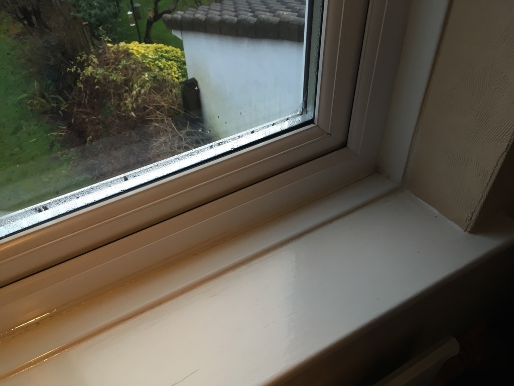
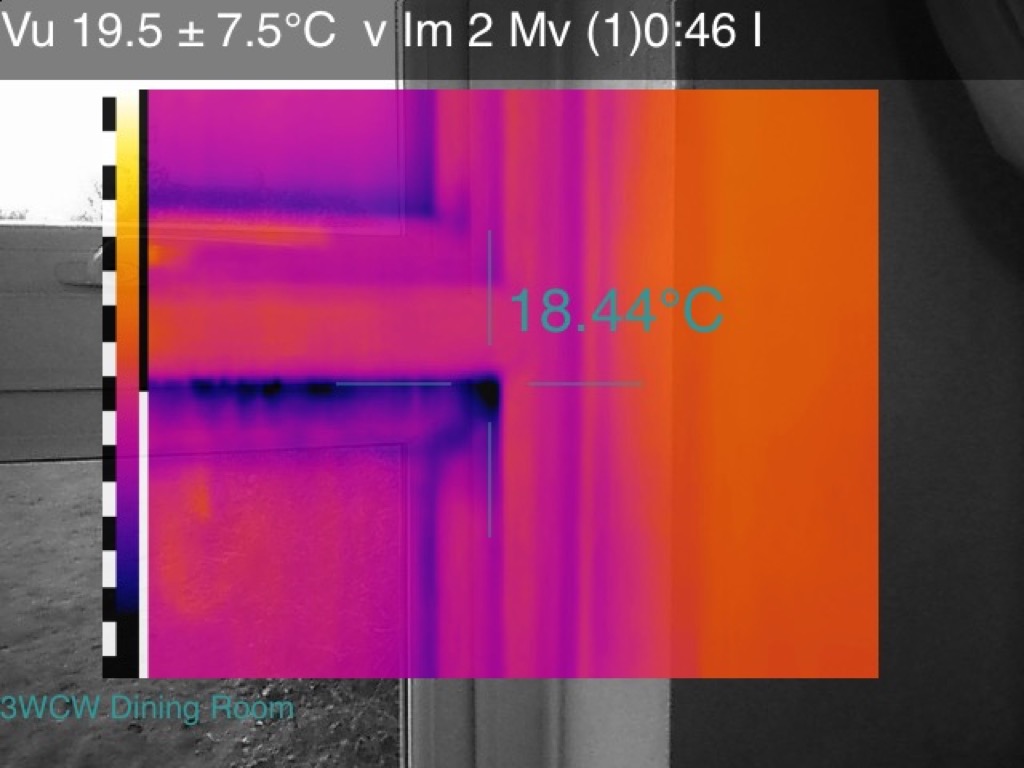
Leaking sill
Related to the lack of sealing of the window frames to the wall was draughts emerging from under the window sill. In the thermal picture below this is particularly visible being above a warm radiator. With the blower door running, it is also easy to feel these with the back of a finger.


Leaking seals
Two opening panes had leaks along part of their seals, where the window did not shut tight to the frame to make it airtight. This was not a significant source of a draught, but a problem that is commonly found with uPVC windows. Often the hinges can be adjusted to remedy this issue, or foam insulation tape could be added.

Missing insulation
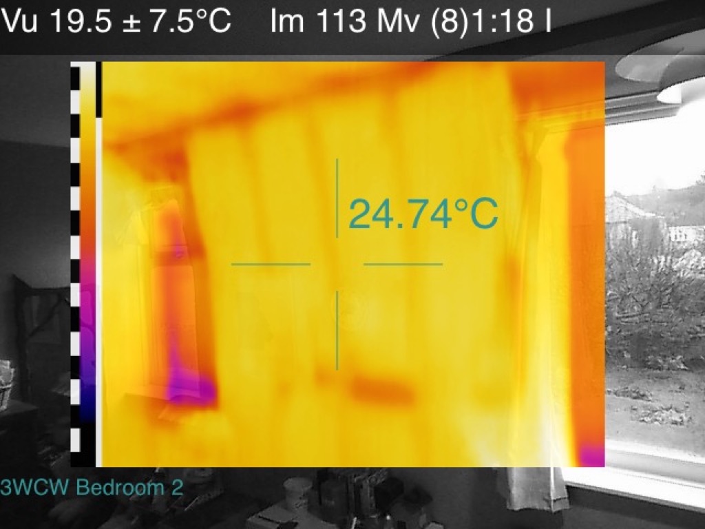
An interesting aspect of the house is that the upper floor has a Mansard roof and is timber construction. The first-floor walls have had insulation inserted behind the tiles, but the thermal picture below shows clearly no insulation has been added above the window. This is the case for all the upstairs windows.

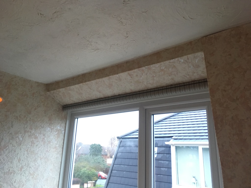
First floor walls
The images below of the first-floor walls show clearly the timber sub structure of the roof and the voids between where insulation has been added. Below the window in the top-left image, there is evidence of air ingress from around the frame into the wall. In the bottom-right image, there is evidence of air ingress from the loft space into the wall, due to missing or lacking insulation at that intersection. In the same picture, you can see a rectangle of missing insulation in the corner. In the bottom-left image, you can see warm walls, the cold window frames and the missing insulation at the top.


By coincidence, a near by Cornish Unit Type 1 house was undergoing some extension work, and has its upper timbers exposed. The picture below shows clearly the construction, and notably the wall voids contained no insulation.

Ground wall
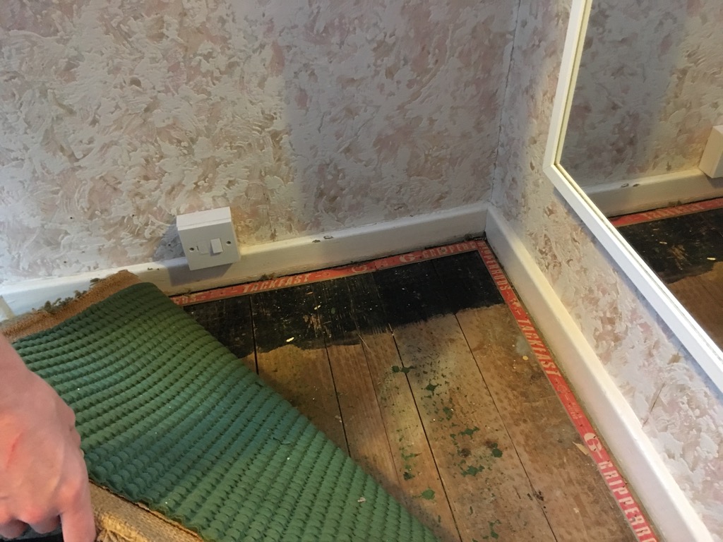
The Mansard roof construction means that the interface between the roof and masonry walls is at the top of the ground floor walls (rather than more conventionally at the top of the upper floor walls). The images below show ingress of cold air from the eaves and into the surrounding wall, stairs and floor. Note also the shape of the block work in the ground floor wall.


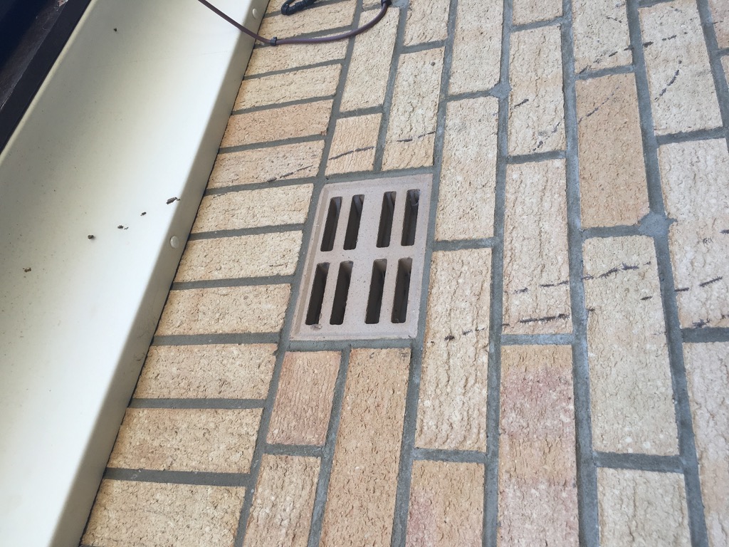
Air brick
The building has one air brick that vents into the wall cavity. This is particularly visible inside, as a cascade of cold air down the wall. Presumably the ventilation is necessary to prevent moisture buildup in the cavity.

Loft hatch
One of the first jobs after moving in was to install a loft ladder for better access to the loft space for storage. The job still requires some finishing touches, but the thermal image shows there is only one main area that requires some additional sealing. Otherwise, I packed more insulation around the frame to resolve the more minor cold patches.

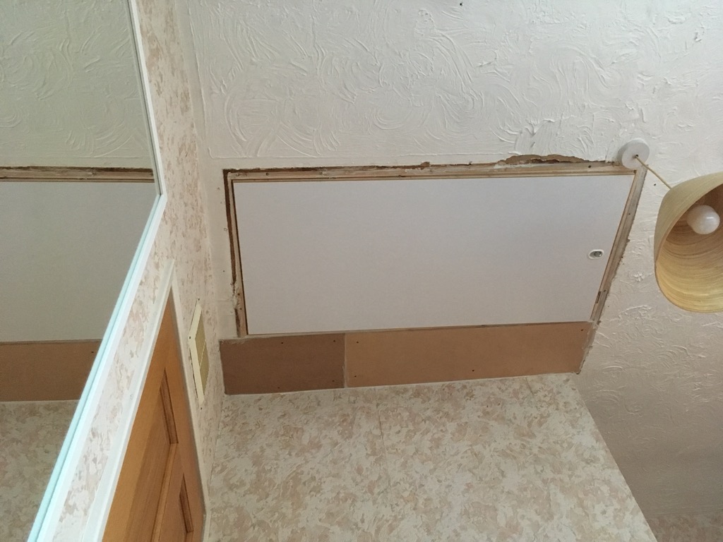
Loft insulation
Due to my work boarding out the loft, there was another piece of missing insulation in the corner (here in the bathroom). These images clearly show the value of loft insulation, and it extending to the edges.

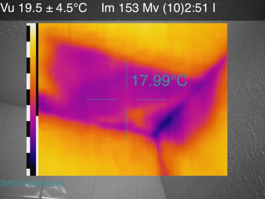
Installing boarding in the loft for storage was a good opportunity to redistribute and top up insulation, and make sure it extended into corners (whilst maintaining space for airflow from the roof). In the right-hand picture, the black columns are stilts that boarding is attached to.


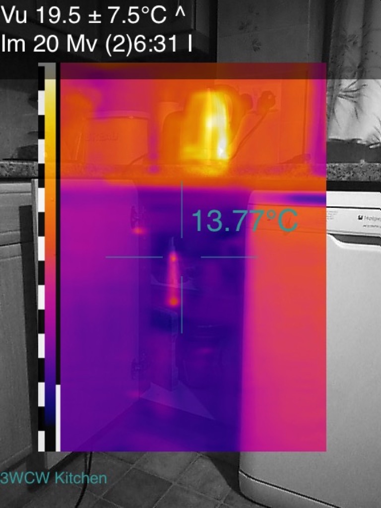
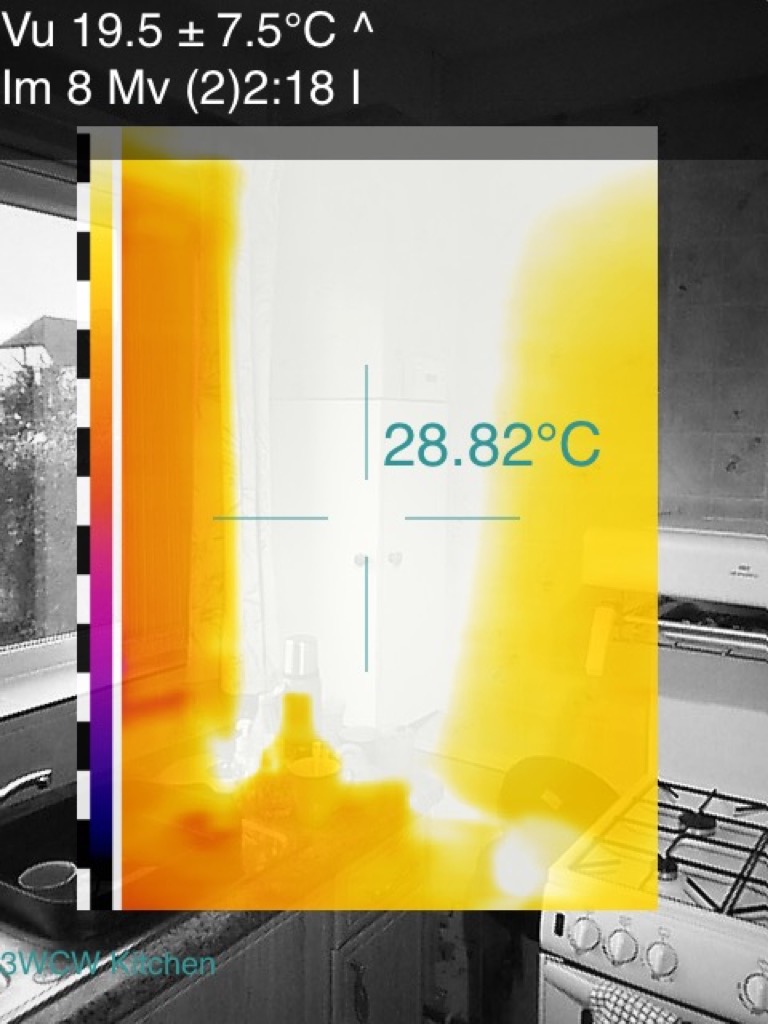
Kitchen
Another particularly cold spot in the house was in a corner of the kitchen, and inside the corner cupboard. This was due to a soil pipe running up through the house to avoid the angle of the Mansard roof, and the boxing carrying it up through the kitchen channelling cold air from the outside. As you can see, the internal temperature of the cupboard was about 10 degrees lower than the ambient room temperature, similar to the front door. I tackled this issue by sealing as much as possible around the boxing and stuffing fibre insulation in all of the remaining gaps. This made a big difference, but a complete fix would require taking the cabinets out and redoing the boxing.

Bathroom
The thermal images in the bathroom did not reveal any significant draughts, but they do show cold air circulating behind the walls. This was confirmed when the bathroom was reorganised, revealing a void behind the sink with plenty of daylight visible through the eaves. Note also in the image of the toilet, the cold water sitting in the cistern.


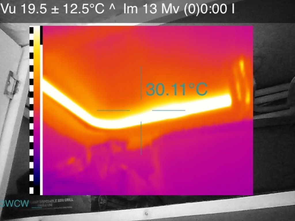
Central heating
It was interesting for the thermal images to reveal the workings of the central heating system. The condensing boiler and its pipework is clearly visible in the top two images. The hot water tank is middle-left, a radiator middle-right and otherwise hidden pipework in the bottom two images.


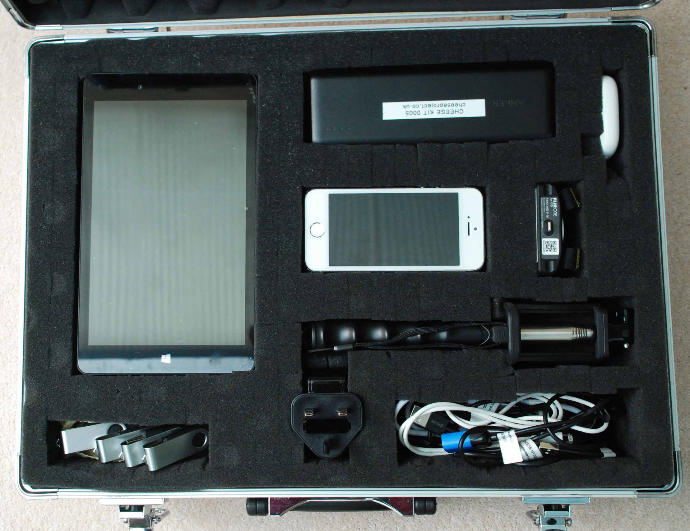
Kit
The left-hand image show the the CHEESE blower door installed on the side door, which precludes that door from being inspected, but it was less of a worry than the front door. The right-hand image shows the CHEESE camera kit, with the iPhone and Flir camera attachment.