
This note describes an LED driver I designed for a lighting project. I decided on a custom solution because I couldn’t find any suitable boards available to buy at a reasonable price. The intended application (which I will describe in another note) requires 12 high-power (~1W) LEDs to be driven individually a 3 by 3 grid measuring approximately 1 metre square, with each of the nine cell containing a red, green, blue and white LED.
I embarked on this project without any experience of designing PCBs, and with relatively little knowledge of electronics, so it was a steep but fantastic learning experience. I wanted to record some of the details of this project for others who may find them useful, as I did with some of the resources I’ve linked to at the end. All of the PCB design files and processor firmware are available on GitHub.
Design
The board is designed around the following main IC components:
-
Microchip PIC12F1572 for PWM LED control and serial communication. This was the simplest PIC I could find that had multiple PWM outputs and UART serial communication capability. It’s an 8-bit device with 16-bit PWMs and 3.5 KBs of program memory.
-
Maxim MAX485 for communication to multiple of these boards. This IC provides half-duplex communication over a 2-wire differential pair using the RS485 protocol, allowing communication over long distances. Importantly it supports multiple drops, so a number of boards can be wired together with a bus. I chose this as it is very simple to integrate, with no additional components required, compared to the capacitors necessary for the MAX232. Talking to the PIC, this can support a baud rate of 115,200 bps.
-
ON Semiconductor CAT4101 for driving LEDs with a constant-current up to 1A with PWM control. Because the temperature fluctuations of high-power LEDs affects their forward voltage, driving them with a constant current is important to avoid damage due to over voltage. These chips neatly integrate this with the PWM control ability. Their only downsides were their cost (~£2 each - with 36 of them needed for my lighting project, they were the greatest single expense) and package which isn’t designed to be hand soldered.
Other features:
-
Header for in-circuit PIC programming. To disconnect the UART pins (required for programming) and to attach a 10K pull up resistor, I included three jumper headers. However, I found connecting the pull up wasn’t necessary for programming.
-
Screw terminals for all installation connections.
-
Indicator LEDs for UART TX and RX directions, and power.
I designed the PCB using the excellent KiCAD and had it manufactured very cheaply by Seeed Studio in Shenzhen, China.
Here’s the schematic:

Parts list
| Quantity | Package | Description |
|---|---|---|
| 3 | TO-263 | CAT4101 LED drivers 5.5V |
| 1 | DIP-8 | PIC12F1572 microcontroller |
| 1 | DIP-8 | MAX485 serial interface |
| 3 | 0805 | Green LEDs |
| 3 | 0805 | Resistor 10K |
| 3 | 0805 | Resistor 1.4K |
| 3 | 0805 | Resistor 510 |
| 5 | 0805 | Capacitor 0.1 uF |
| 3 | SOT-23 | 2N7002 N-channel MOSFET 300 mA |
| 4 | - | 2 way 5mm pitch terminal blocks |
| 1 | - | 3 way 5mm pitch terminal blocks |
| 12 | - | 2.54mm pitch pin headers |
| 3 | - | 2.54mm pin header jumper caps |
The CAT4101 sense resistors are chosen to give a constant current close to 300 mA, at 1.4 KOhms. See the CAT4101 datasheet for more details.
For reference, I have assumed the following parameters of the LEDs I used (you should however check the datasheet for a particular LED):
| Colour | Typical forward voltage (@ 350 mA) |
Part | Reference |
|---|---|---|---|
| Red | 2.4 | 3W RGB module | Datasheet (PDF) |
| Green | 3.4 | 3W RGB module | Datasheet (PDF) |
| Blue | 3.5 | 3W RGB module | Datasheet (PDF) |
| White | 2.8-3.4 | 1W Ice White LED (Bridgelux 9000-15000k) | Future Eden |
The CAT4101 is a linear driver, so it effectively acts as a variable resistor to deliver constant current, with an efficiency of $V_{led}/V_{supply}$. A disadvantage of driving each LED individually is that its efficiency can be low, down to 50%. The power delivered to the LED is $I_{led} \times V_{led}$ and the power dissipated by the driver is $I_{led} \times V_{supply}$ (not including quiescent power).
| Channel | Voltage (V) | Current (A) | LED power (W) | CAT4101 efficiency | Driver power (W) |
|---|---|---|---|---|---|
| Red | 2.4 | 0.3 | 0.72 | 0.48 | 1.5 |
| Green | 3.4 | 0.3 | 1.02 | 0.68 | 1.5 |
| Blue | 3.5 | 0.3 | 1.05 | 0.7 | 1.5 |
| White | 3.2 | 0.3 | 0.96 | 0.64 | 1.5 |
Measurements of each of the LED channels using a current clamp meter showed that the current drawn ranges from 357 mA to 370 mA.
Programming
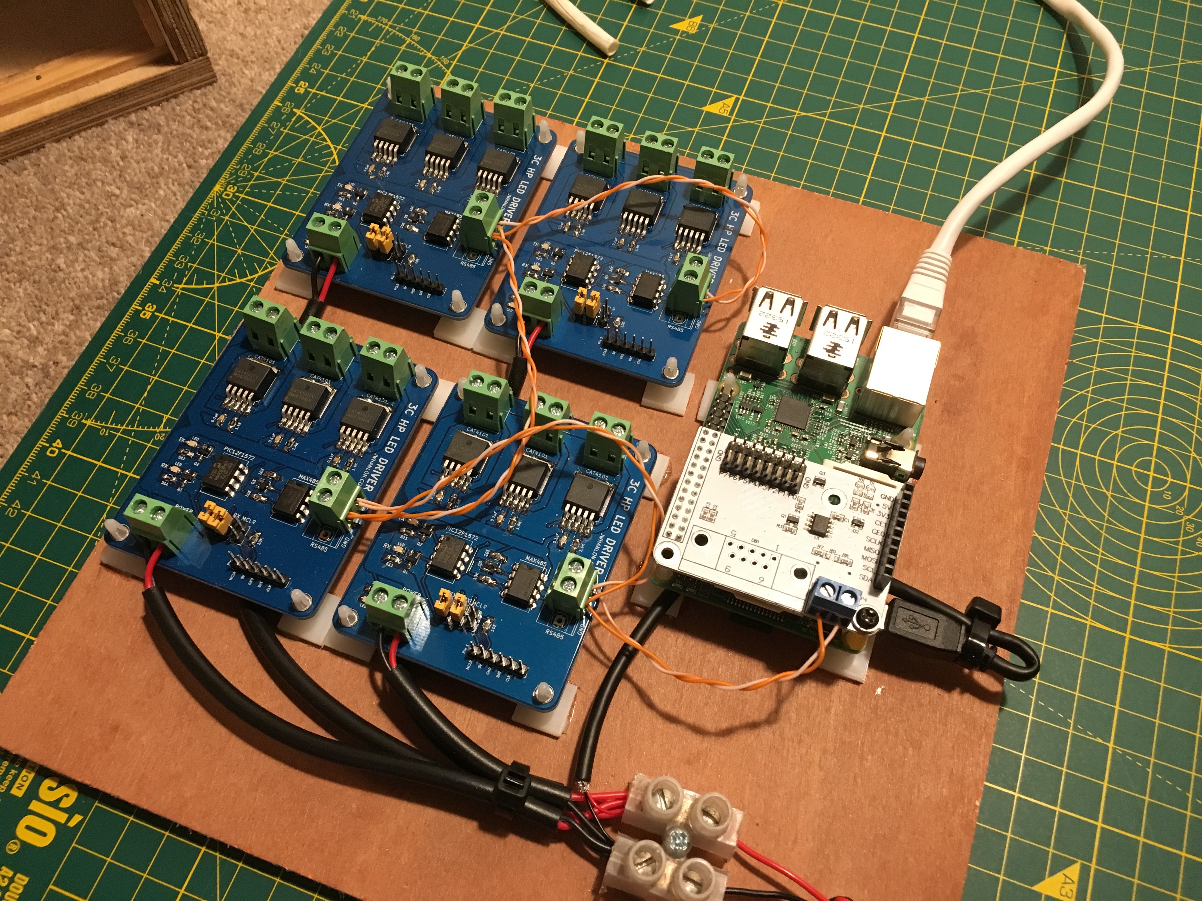
The intention of the PIC microcontrollers is to react to a simple set of commands sent via the serial interface. In deployment, an array of these driver boards would be controlled by another processor broadcasting on the RS485 bus. I used a Raspberry Pi with an RS485 shield to do this.
At a minimum, the PICs need to set the intensity of each LED they control, which is the current operation of the firmware. They could however be triggered to perform more complex modulations. This would reduce the data transmission requirements on the RS485 bus, potentially improving the quality of animations produced by an array.
The PIC microcontrollers are programmed in C, which I did using Microchip’s XC compiler and MPLab IDE software. In order that each board can uniquely identify it’s control data, they are compiled with a unique ID. With a deployment of 12 boards, firmware updates are a little arduous, particularly since the two jumpers need to be removed as well.
I found that an efficient communication protocol between an array of boards and the main controller (Raspberry Pi) is a sequence of bytes with the first uniquely determining the header and the following 36 determining the intensity of each of the individual LEDs. Each board uses its ID to choose three values in the payload. At 115,200 bps, this in theory allows up to 389 commands to be sent per second. Note that the boards do not send an acknowledgement, since this significantly reduces the throughput. In Python a packet can be sent with (snippet from here):
def set_colour(payload):
    assert len(payload) == (3*12)
    usart.write(bytearray([chr(255)]+payload))
    usart.flush()
The PICs receive UART data and set the output PWMs thus (snippet from here):
...
// Reset if we see the start of packet marker.
if (RCREGbits.RCREG == START_PACKET) {
  uart_count = 0;
} else {
  // Packet payload.
  uart_data[uart_count++] = RCREGbits.RCREG;
  // When we've received the payload, update PWMs and setup for next packet.
  if (uart_count == PAYLOAD_SIZE) {
    // Set the duty cycles, scale an 8-bit range into 16 bits.
    PWM1DC = uart_data[DRIVER_OFFSET+0] * 256;
    PWM2DC = uart_data[DRIVER_OFFSET+1] * 256;
    PWM3DC = uart_data[DRIVER_OFFSET+2] * 256;
    // Reload the PWMs.
    PWM1LD = 1;
    PWM2LD = 1;
    PWM3LD = 1;
    uart_count = 0;
  }
}
...
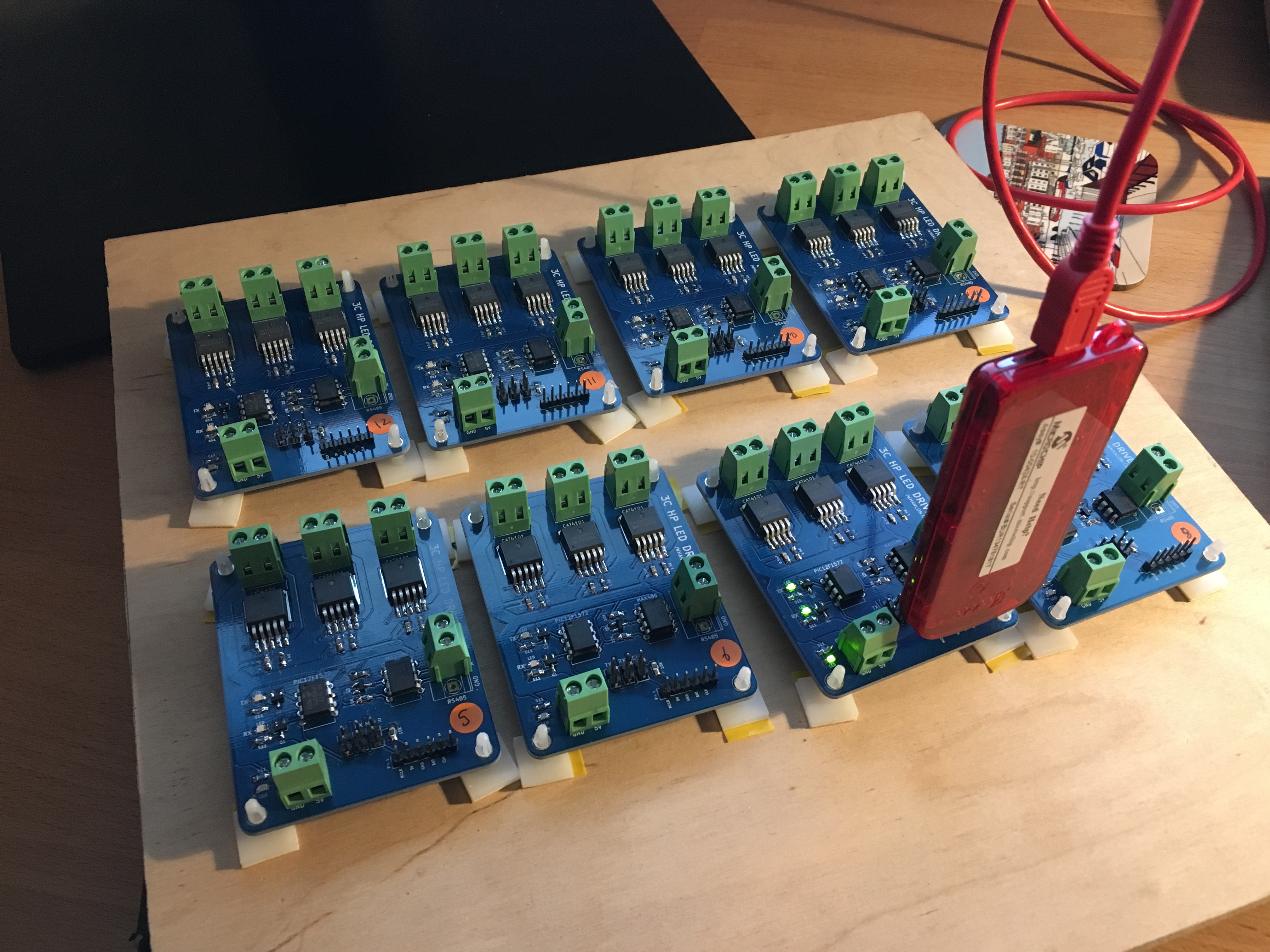
Pictures


Improvements
- Adjust the CAT4101 sense resistor to deliver closer to 300 mA (1.5-1.6 KOhm).
- Remove the 10K pull up resistor for programming the PIC since it is unnecessary.
- Update the defunct silk screen URL to my new jameswhanlon.com domain.
References
- Board design and microcontroller source code on GitHub
- RGBW LED Controller v3.1 (The Custom Geek).
- Make an RGB lighting controller (Bigclivedotcom)
- Easy CAT4101 LED Driver (Instructables)
- High power LED driver circuits (Instructables)
- Power LED’s - Simplest Light With Constant-current Circuit (Instructables)
- Re: Help understanding electrical efficiency of LEDs with PWM dimming (Candle Power Forums)