
The ‘RGB stacks’ lightboxes are an experiment with using high-power LEDs, generous volumes and translucent acrylic plastic to create big blocks of colour. They are constructed from 12 mm birch ply and each pixel measures 300 x 300 (outer dimensions). They are built as three columns of three pixels to allow them to be arranged in a square, a line, or in different locations. This note records some of the details of their construction. Although they are now functional, refinement of their controls and modulation continues to be a work in progress. This note records some of the details of how they were built (I will it updated with any new developments).
The project was inspired by a similar light box project (that unfortunately I can no longer find on the internet), but which was a single 3 x 3 cabinet achieving a similar block-colour effect. My motivation was to build something similar but that could also be used as subtle/ambient lighting, making use of the amazing colours and ability to accurately modulate LEDs to create smooth transitions between rich colours and interesting combinations.


Construction of the stacks was straightforward: all panel dimensions are multiples of 300 and all joints biscuited and glued to avoid any visible fixings. (I unfortunately don’t have any pictures of the construction of the stacks.)


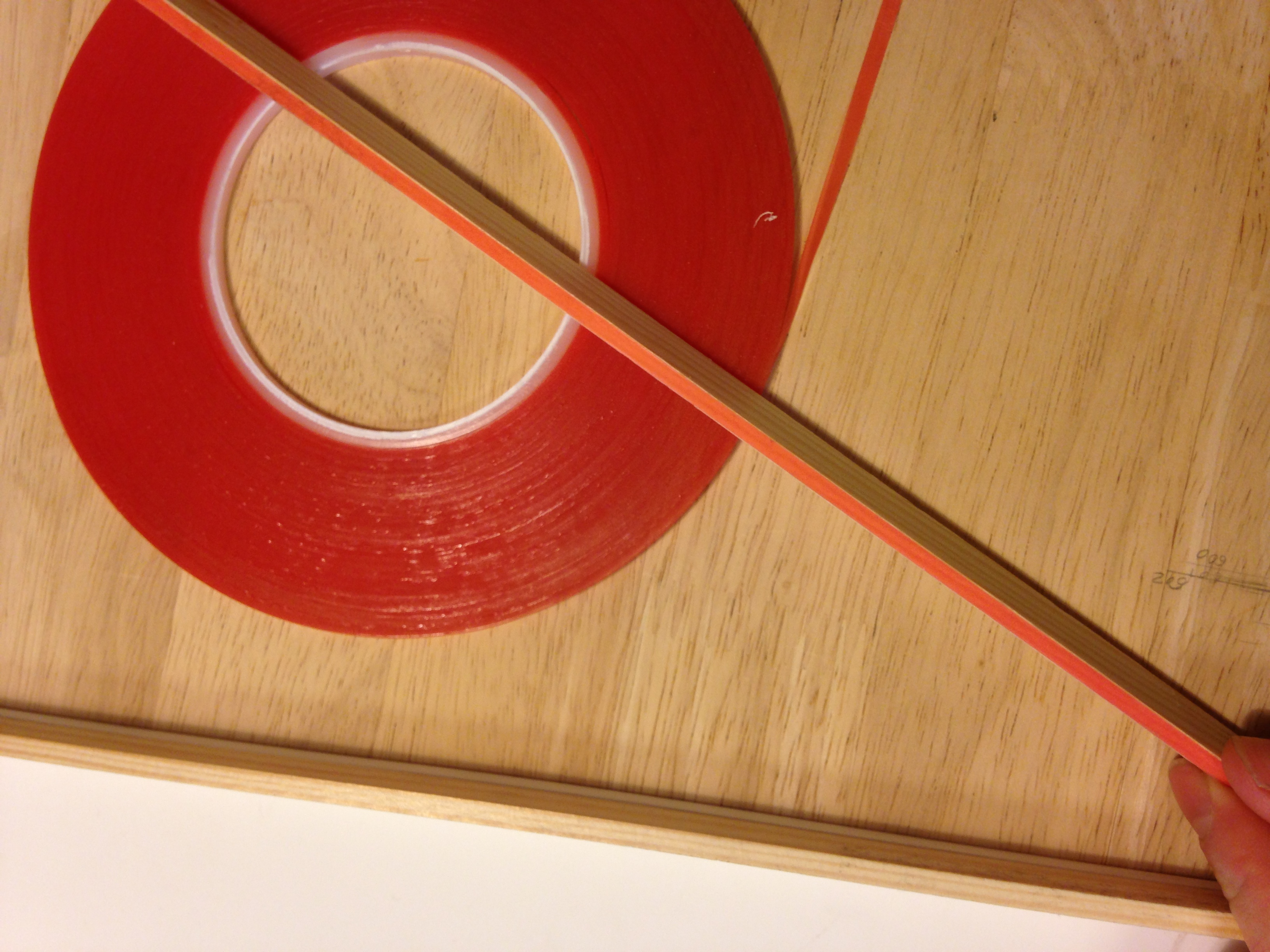
The acrylic panels were cut to fit the inner box dimensions exactly, but with small variations in the dimensions of the boxes. Getting them all to fit was a long process of sanding down each one to fit a particular opening. A secure fit of the panels was achieved with tight tolerances and narrow double-sided sticky tape (pictured above right).

Pairs of white and RGB LEDs were mounted on aluminium bar in each pixel. The LED were fixed in place with small bolts. I made small plastic washers to avoid shorting any of the contacts with the bolt heads. Although the aluminium bar probably provides a sufficient heat sink, I added additional heatsink blocks on the rear side, fixed with thermal glue (these were cut up from larger IC heatsinks). All of the LED wiring was conveniently done with CAT6 cable, using all of the eight cores to wire the four channels. Each channel draws about 1 W at 5 V (200 mA), which is within the specification of the CAT6.


Each box has a rear plug panel. The central box acts as a master and has connections for power, Ethernet, and provides serial data and power to the other outer boxes.


The inter-box wiring uses 5-pin XLR sockets, to carry power, ground and the differential pair for the serial signal. The wires were made with a dual-core power wire (sufficient to carry the required power at 5V) with a another dual-core wire for the serial, wrapped in a heatshrink coat.

The electronics for the LED drivers is described in a separate note. Each of the LED driver boards has three outputs, so four boards are required to drive a single stack. The Raspberry Pi microcontroller is used to control all the pixels, and does so with a dual-wire RS-485 serial bus. This bus connects each of the driver boards in series, and the outer boxes are wired in parallel. Despite some concerns about this topology from notes on the MAX-485 driver IC datasheet and that I didn’t use terminating resistors, the arrangement performs fine.
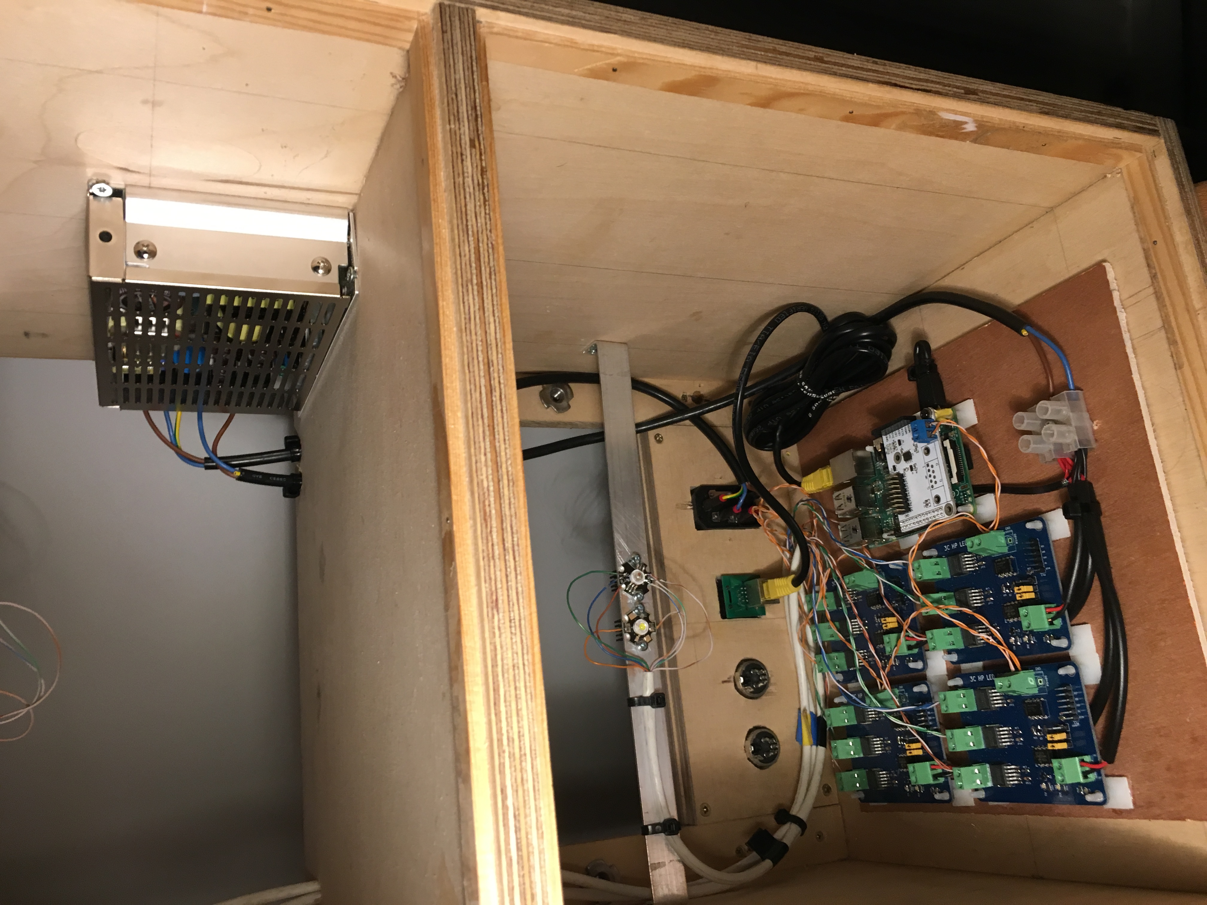
So that I could easily access the electronics, I integrated the drivers and their wiring on a plywood board that sits in the base of a stack. The master stack has the power supply, taking mains voltage and providing 5V up to 60W (12A) for the three stacks. See the table below for calculated power of the LEDs only. Note that the power supply does not output enough power do drive the boxes comfortably (80W would be more comfortable).
| Channel | Voltage (V) | Current (A) | LED power (W) | Driver efficiency | Driver power (W) |
|---|---|---|---|---|---|
| Red | 2.4 | 0.3 | 0.72 | 0.48 | 1.5 |
| Green | 3.4 | 0.3 | 1.02 | 0.68 | 1.5 |
| Blue | 3.5 | 0.3 | 1.05 | 0.7 | 1.5 |
| White | 3.2 | 0.3 | 0.96 | 0.64 | 1.5 |
| Total (per pixel) | - | - | 3.75 | - | 6 |
| Total (per stack) | - | - | 11.25 | - | 18 |
| Total | - | - | 33.75 | - | 54 |
To check the above power numbers I performed some measurments with a clamp meter of the central stack:
- With all LEDs off, the quiesence current is 360 mA at 5 V, dissipating 1.8 W.
- With all LEDs on at full intensity, the current is 4.75 A at 5 V, dissipating 23.75 W.
These numbers are slightly higher than expected, due to the LED driver current ranging between 0.357 mA (blue) and 0.370 mA (green).


The back panels fasten with M8 bolts into T-nuts.


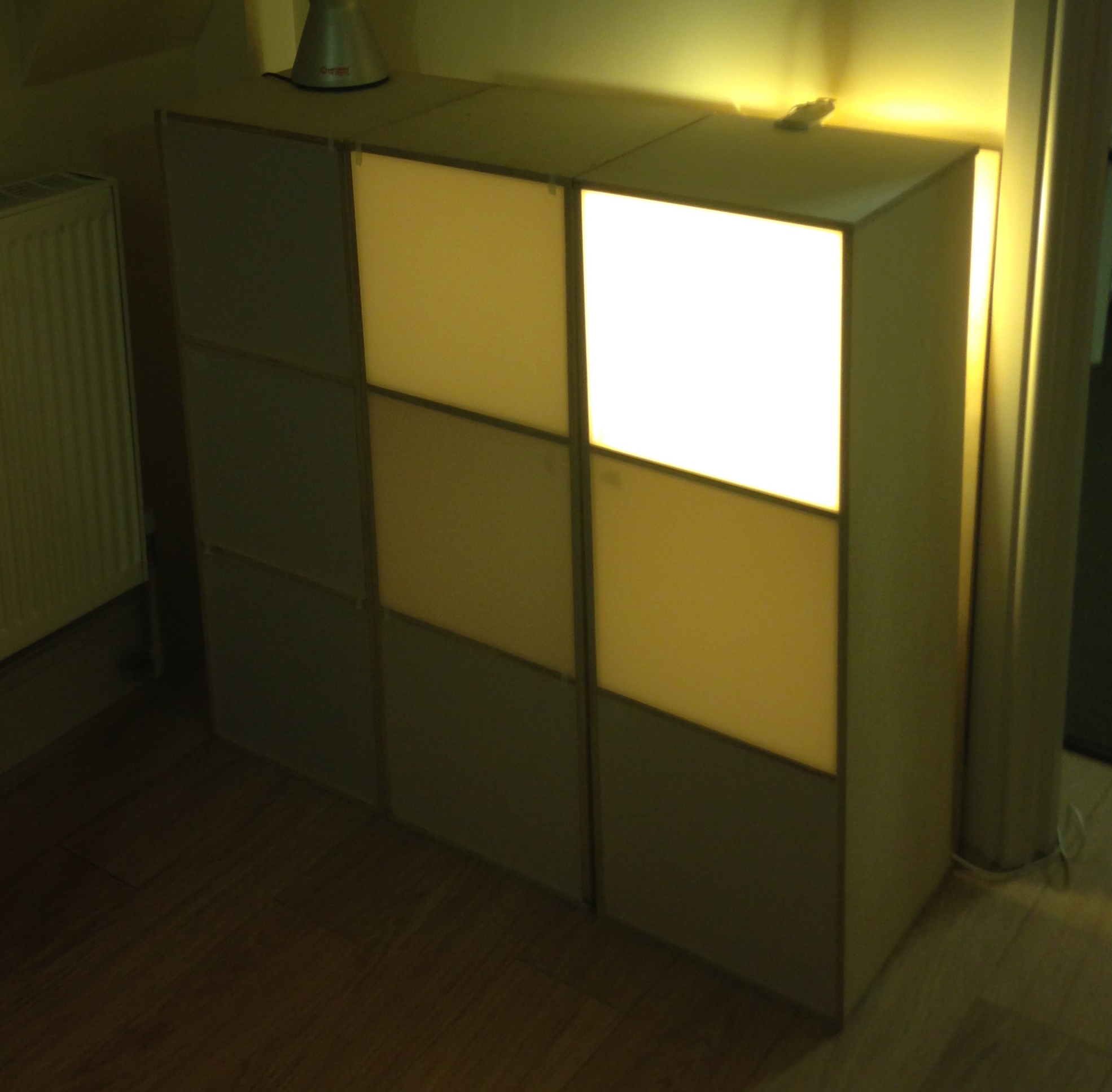
It’s hard to capture the quality of the effect of the light boxes on camera. The images below are two early tests: left just using a lamp in one of the pixels, right with no blending of the RGB channels.

The behaviour of the boxes is determined by the PIC programs and the Raspberry Pi. Since changes to the PIC program requires each of the boards to be programmed individually and for each program to be compiled with a unique identifier, this is not an easy way to experiment with modulating schemes. Instead, each PIC is programmed only to change the output intensity, and experimentation can be done using Python on the Raspberry Pi over SSH. In these scheme, updates are sent to the LED drivers synchronously, as a frame. At 115,200 bps baud rate over RS485, this is sufficient to deliver up to 389 updates per second. In practice there are overheads that will reduce this. If, for smooth graduations between colours the frame rate was not adequate, an optimisation could be to expand the capability of the PIC driver code to perform more complex actions like sweeps over intensity ranges, thereby reducing the number of updates required.
As I mentioned, these boxes are not yet complete. To finish them, I want to add a button panel to switch them on off and control the lighting patterns.